the smac framework
( System Monitor and Control )
SMAC is a fast, wireless, bidirectional system similar to a SCADA System!
It allows you to monitor and control your devices from a browser.

Features
Telemetry
Acquire and visualize data
from sensors and equipment.
Acquire and visualize data
from sensors and equipment.

Control
Operate devices, robots
and automation equipment.
Operate devices, robots
and automation equipment.

Scalable
A SMAC System can be as simple as
a single temperature probe or as complex
as an entire factory of machines.
A SMAC System can be as simple as
a single temperature probe or as complex
as an entire factory of machines.

architecture
SMAC consists of one or more microcontroller-based remote modules called "Nodes"
that connect to sensors and equipment. These Nodes wirelessly communicate
with the "SMAC Relayer" module using a specialized protocol. The Relayer
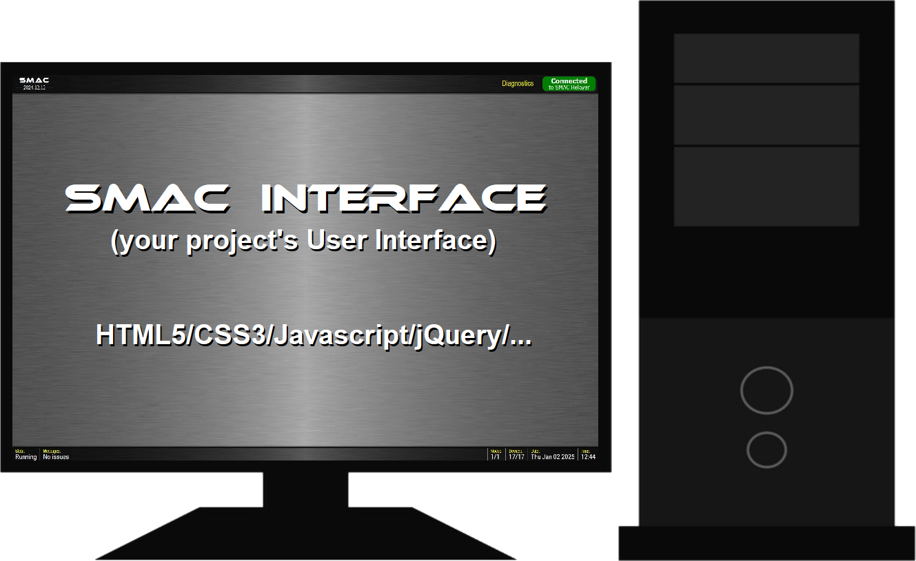
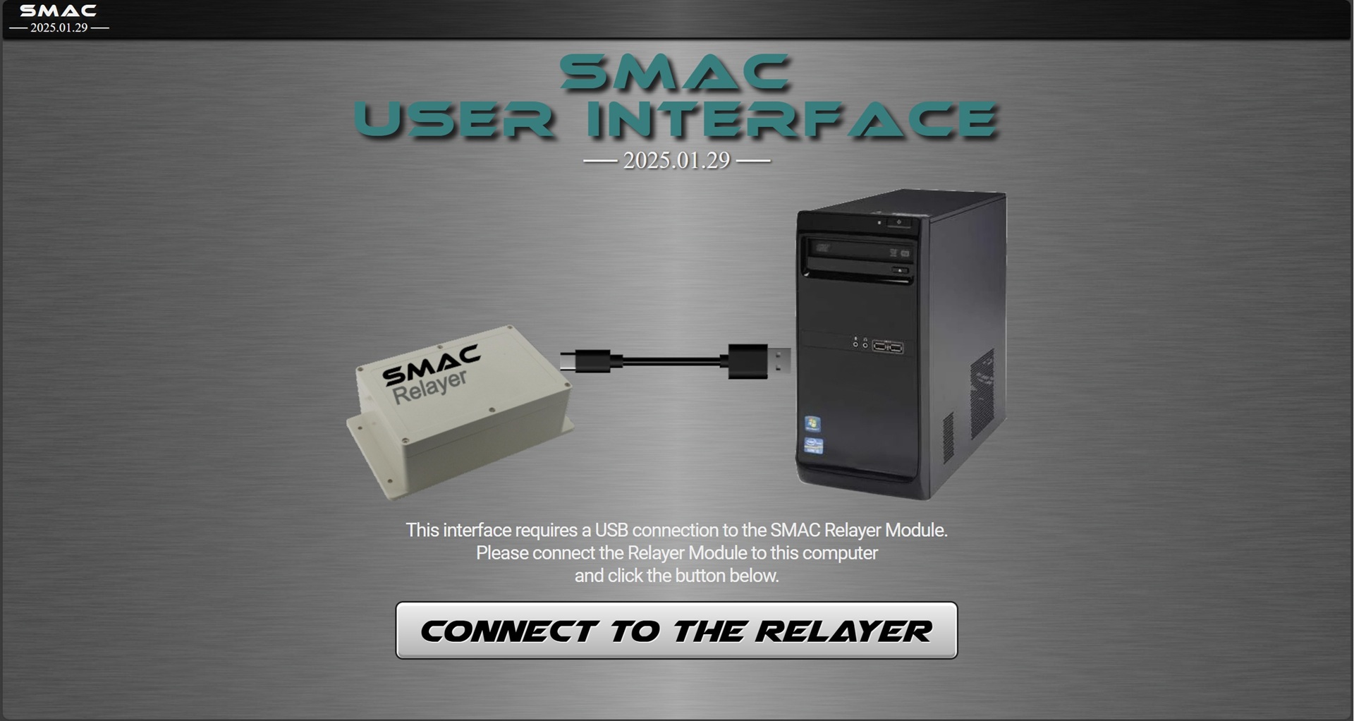
is a wired USB device that "relays" Node/Device data to the "SMAC User Interface" on a PC.
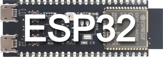
The recommended microcontroller is an ESP32 development board such as the Espressif ESP32-S3-DevKitC-1.
The recommended microcontroller is an ESP32 development board such as the Espressif ESP32-S3-DevKitC-1.
- A single Node can interface with multiple sensors and equipment. For example, a Node can connect to a three-section pizza oven, monitor the temperatures of each section and control the heat coils of each section. It could also control the conveyor moving the pizza through the oven.
- Nearly any type of analog or digital equipment, sensor or motor driver can be connected to a Node for data monitoring, command instruction or drive control.
- Up to twenty Nodes can be used in a SMAC System. So an entire factory of sensors and equipment can be examined and controlled.
- Nodes wirelessly communicate with a "Relayer Module" over WiFi using the ESP-NOW Protocol by Espressif. The Relayer directly connects to a PC via USB.
- The PC runs the "SMAC Interface" using the Chrome or Edge Web Browser.
- The SMAC Interface allows users to both graphically visualize data and control equipment. Data can be viewed using animated bar charts, gauges, graphs and more. Equipment can be controlled using buttons, switches, sliders, dials, etc. - very similar to industrial control panels.
Equipment, Sensors, Motor Drivers, etc.
N O D E

N O D E


N O D E


● ● ●
up to 20 Nodes
up to 20 Nodes
Fast, Wireless
ESP-NOW
WiFi Communications
R E L A Y E R


nodes
Hardware
In its simplest form a Node is an ESP32 development board running Node/Device firmware.
It can be powered by a 5V A/C adapter (wall wart) or a battery system.
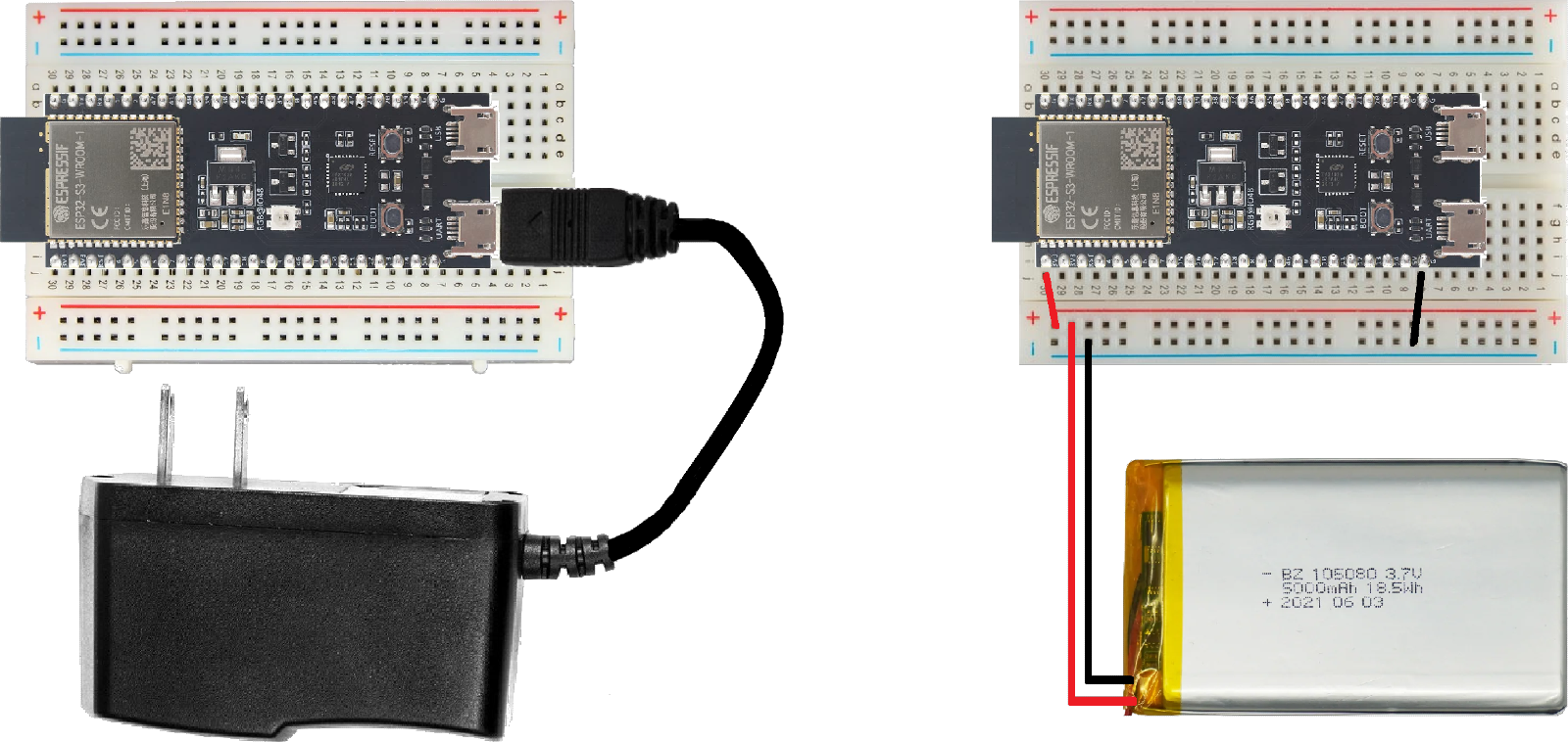
The Espressif ESP32-S3-DevKitC-1 board has an RGB LED onboard. It is used as a status indicator at power up. When the Node first powers up and begins initializing, it will be RED. When the Node establishes communications with the Relayer Module, it will turn GREEN to indicate the Node is ready. (More about the Relayer below)
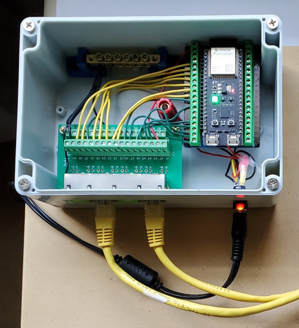
Your sensors and devices will use the GPIO pins of the Node's ESP32 board. You can operate up to 100 devices but you're more likely to run out of GPIO pins well before that. As you develop your gizmo, you may want to enclose your electronics and provide connectors to external devices. (If you use an ESP32 with a PCB antenna, it is not recommended to use a metal enclosure.)
Connection to your equipment and devices is up to you, but here's an example of a Node enclosure using an RJ-45 Breakout Board and a barrel jack for the 5V power adapter.
Firmware
The Node/Device firmware is written in C++ and includes "Node" and "Device" base classes. The Node object creates the Devices it will use.
It is rare that you will need to derive a child class from Node but your custom Devices should always be derived from the Device base class.
  Node
  Device
    │
    ├── MyCustomDevice1
    ├── MyCustomDevice2
    :
You create your Node in the setup of your .ino (or main.cpp) file.
After constructing a Node with a name and unique ID (0-19), you "add" Devices using the Node's
AddDevice() method. All Devices added to your Node will be assigned a unique ID (0-99).
The Device ID is assigned automatically when your Device is added to the Node.
void setup ()
{
:
:
ThisNode = new Node ("My First Node", 0);
ThisNode->AddDevice (new MyCustomDevice1 (...));
ThisNode->AddDevice (new MyCustomDevice2 (...));
:
:
}
Then you "Run" the Node in the main loop.
void loop ()
{
ThisNode->Run ();
}
The Node's Run() method continually calls the DoImmediate() and DoPeriodic() methods for all Devices. It keeps your SMAC System running. More on that in the Devices section below ...
Nodes can handle "Commands" sent from the SMAC Interface, although most commands are intended for Devices. Commands are four characters with optional parameters and are usually targeted for a specific Device.
The Node base class handles the following built-in commands but a derived Node can handle custom commands by overriding the Node's ExecuteCommand() method.
  SNNA = Set Node Name
  GNOI = Get Node Info   : DataPacket.value = name|version|macAddress|numDevices
  GDEI = Get Device Info : DataPacket.value = name1|rate1|name2|rate2|...
  PING = Check if still alive and connected; responds with "PONG"
  BLIN = Quickly blink the Node's status LED to indicate communication or location
  RSET = Reset this Node's processor using esp_restart()
Your custom Node class should first call the base class's ExecuteCommand() method to handle the
built-in Node commands:
Node::ExecuteCommand (...);
The ExecuteCommand() method returns a "ProcessStatus" and may return a value of "NOT_HANDLED". If the command is not handled by the base class, you can handle the command in your derived class. More about "ProcessStatus" below.
devices
Your custom Device should be derived from the Device base class.
Devices can perform two kinds of operation: an "Immediate Process" and a "Periodic Process".
An Immediate Process is a quick operation you want your Device to do continuously with as little delay as possible between operations. For example, checking if a physical button is being pressed on a control panel.
A Periodic Process is an operation to be performed at a periodic rate such as reading a sensor once per second.
You define your Immediate Process by overriding the DoImmediate() method.
You define your Periodic Process by overriding the DoPeriodic() method.
The rate of calls to DoPeriodic() is set in "calls per hour" using the Device's SetRate() method. It defaults to 3600 (one call per second).
      1 = one call per hour   (the slowest data rate)
     60 = one call per minute (for example, a temperature plot for a day)
   3600 = one call per second (default)
  72000 = 20 calls per second (recommended fastest data rate)
All data is sent to the Relayer (and on to the SMAC Interface) by populating the
global <DataPacket> structure and returning an appropriate "ProcessStatus".The <DataPacket> structure has three fields:
  deviceID  : 2-char string (00-99)
  timestamp : timestamp of when the data was acquired - usually millis()
  value     : variable length string (including NULL terminating char)
              (this can be a numerical value or a text message up to 240 chars)
For the DoPeriodic() method, we only need to populate the timestamp
and value fields. The deviceID is filled for us by the Node base class.
DataPacket.value must be a NULL terminated string!Both the DoImmediate() and DoPeriodic() methods return a "ProcessStatus" enum value.
It can be one of four values:
  SUCCESS_DATA    - Process performed successfully, send DataPacket to Relayer (such as a sensor reading)
  SUCCESS_NODATA  - Process performed successfully, no data to send to Relayer
  FAIL_DATA       - Process failed, send DataPacket to Relayer (such as error code or message)
  FAIL_NODATA     - Process failed, no data to send to Relayer
Here is a template for returning data in your DoPeriodic() method:
//--- DoPeriodic (override) -------------------------------
ProcessStatus LightSensor::DoPeriodic ()
{
// The "Periodic Process" for this device is simply to measure a sample
int sample = 4095 - analogRead (sensorPin);
// All data is returned by populating the global <DataPacket> structure
// and returning an appropriate ProcessStatus.
//
// The <DataPacket> structure has three fields:
//
// deviceID : 2-char string (00-99)
// timestamp : timestamp of when the data was aquired - usually millis() converted to a string
// value : variable length string (including NULL terminating char)
// (this can be a numerical value or a text message)
// For the DoPeriodic() method, we only need to populate the timestamp
// and value fields. The deviceID is filled for us by the Node base class.
DataPacket.timestamp = millis ();
itoa (sample, DataPacket.value, 10); // DataPacket.value must be a terminated string
// DoPeriodic() must return one of four possible "ProcessStatus" values:
//
// SUCCESS_DATA - Process performed successfully, send DataPacket to Relayer (such as a sensor reading)
// SUCCESS_NODATA - Process performed successfully, no data to send to Relayer
// FAIL_DATA - Process failed, send DataPacket to Relayer (such as error code or message)
// FAIL_NODATA - Process failed, no data to send to Relayer
// For this example, we indicate a successful reading with data to send
return SUCCESS_DATA;
}
Like Nodes, Devices can execute commands. Your Device can execute custom commands by overriding the Device's ExecuteCommand() method.
Node/Device Commands are sent from the SMAC Interface as a text string. The command string has four fields separated with the '|' char for clarity and has the following format:
  ┌─────────────── 2-char nodeID (00-19)
  │  ┌──────────── 2-char deviceID (00-99)
  │  │   ┌──────── 4-char command (usually capital letters)
  │  │   │     ┌── Optional variable length parameter string
  │  │   │     │
  nn|dd|CCCC|params
The Device base class handles the following built-in commands:
  GDNA = Get Device Name              : Returns this device's name
  SDNA = Set Device Name              : Sets this device's name (a User-Friendly name for the SMAC Interface)
  ENIP = Enable Immediate Processing  : Start executing the immediate process for this device
  DIIP = Disable Immediate Processing : Stop executing the immediate process for this device
  DOIP = Do Immediate Process         : Perform the immediate process one time
  ENPP = Enable Periodic Processing   : Start executing the periodic process for this device (start sending data) default
  DIPP = Disable Periodic Processing  : Stop executing the periodic process for this device (stop sending data)
  DOPP = Do Periodic Process          : Perform the periodic process one time, returns true or false
  GRAT = Get Rate                     : Get the current periodic process rate for this device in calls per hour
  SRAT = Set Rate                     : Set the periodic process rate for this device in procs per hour
Your custom Device class can override ExecuteCommand() to handle custom commands,
for example, CALI for a calibrate function. It should first call the base class's
ExecuteCommand() method to handle the built-in Device commands. More on this in the examples.The ExecuteCommand() method returns a "ProcessStatus" and may return a value of "NOT_HANDLED". If the command is not handled by the base class, you can handle the command in your derived class.
Here is a template for handling custom commands in your ExecuteCommand() method:
//--- ExecuteCommand (override) ---------------------------
ProcessStatus LED::ExecuteCommand ()
{
// Command info is held in the global <CommandPacket> structure.
// This method is only called for commands targeted for this device.
// First call the base class ExecuteCommand method
pStatus = Device::ExecuteCommand ();
// Check if command was handled by the base class
if (pStatus == NOT_HANDLED)
{
// The command was NOT handled by the base class,
// so handle custom commands:
//--- Turn On ---
if (strcmp (CommandPacket.command, "LEON") == 0)
{
// Turn on the LED pin
digitalWrite (ledPin, HIGH);
// Indicate successful and no data to return
pStatus = SUCCESS_NODATA;
}
//--- Turn Off ---
else if (strcmp (CommandPacket.command, "LEOF") == 0)
{
// Turn off the LED pin
digitalWrite (ledPin, LOW);
// Indicate successful and no data to return
pStatus = SUCCESS_NODATA;
}
}
// Return the resulting ProcessStatus
return pStatus;
}
the relayer
The SMAC Relayer is just an empty ESP32-S3 board with the Relayer firmware flashed to it. The board should have its USB connector exposed so it can be cabled directly to a PC or laptop.
The Relayer could even be an ESP32 USB Dongle!

Other than possibly needing to change the LED pin number there is no custom code needed for the Relayer.
Just flash the Relayer firmware to an ESP32 board and you'll have a working Relayer ready to go.
the smac interface
The SMAC Interface is a web app that lets you monitor data and control equipment using the Chrome or Edge web browser.
It receives DataPackets and sends CommandStrings from/to all your Nodes and Devices.
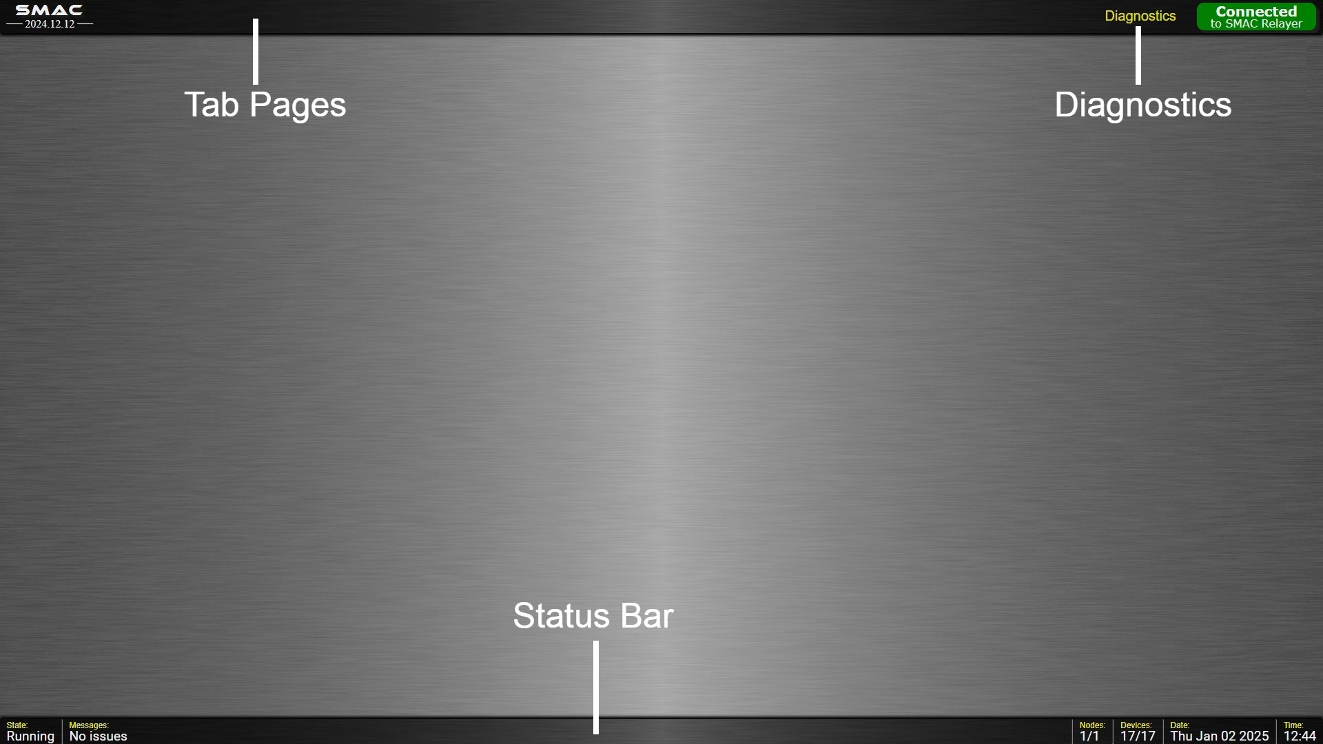
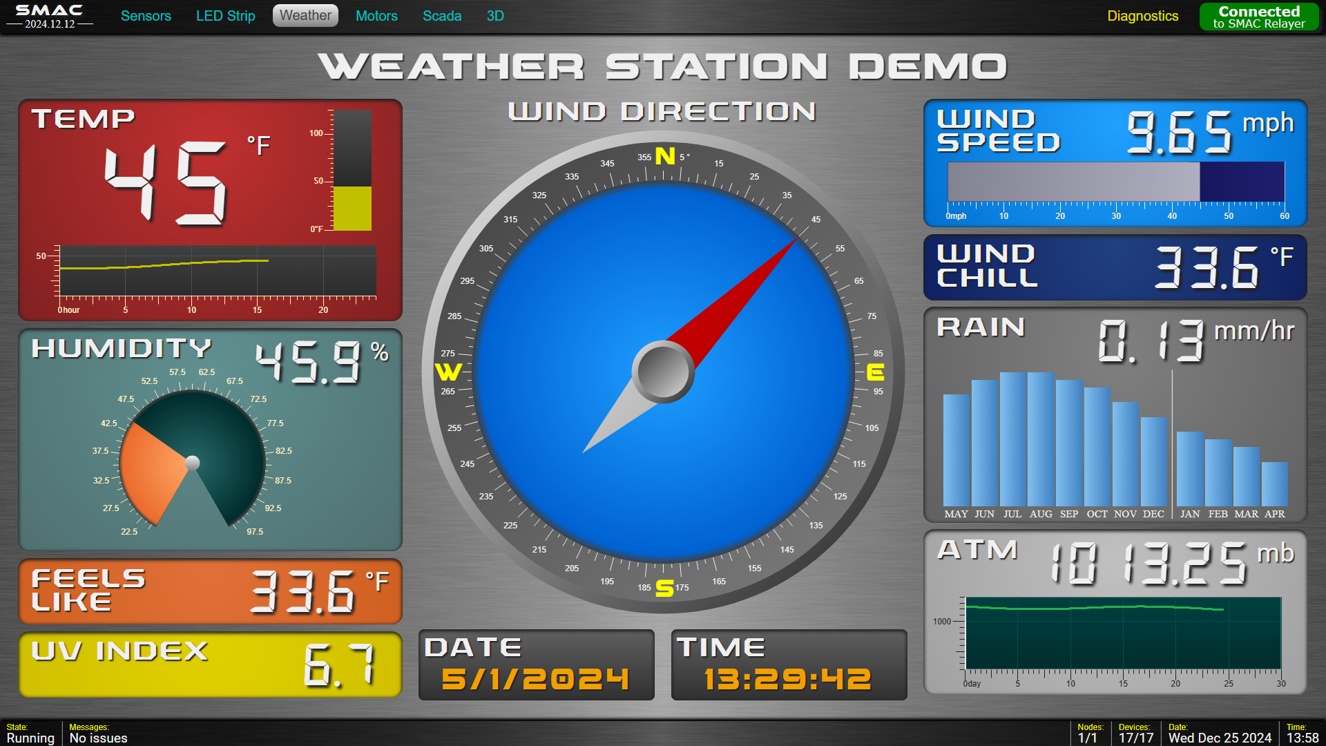
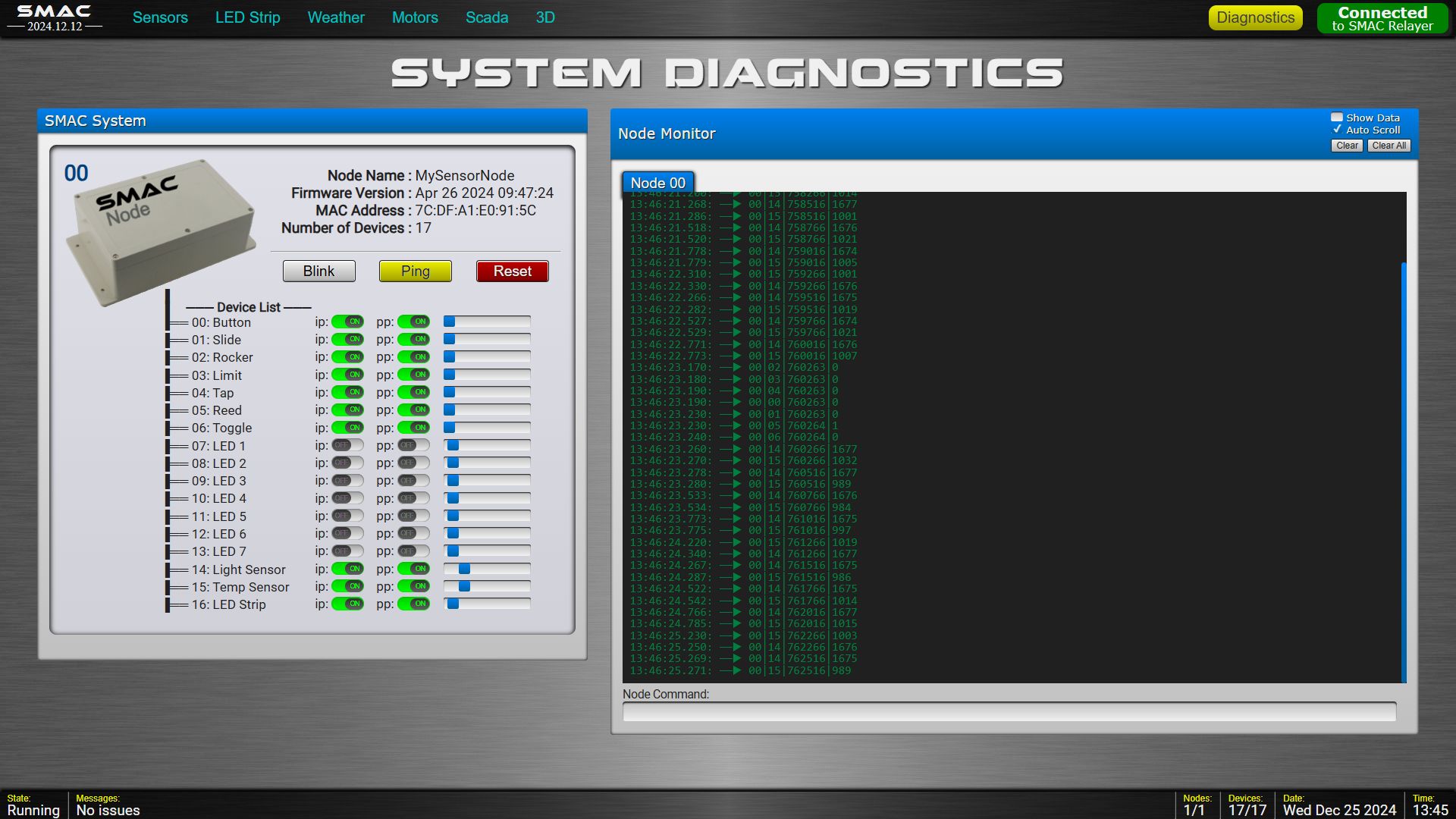
The SMAC Interface can host multiple pages, or "sections", of your interface using a tabbed control in the top header. Included is a Diagnostics tab that displays all the Nodes and Devices connected to your system as well as a Data Monitor for each of the Nodes.
Some Examples
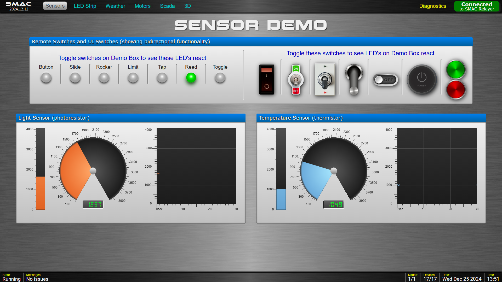
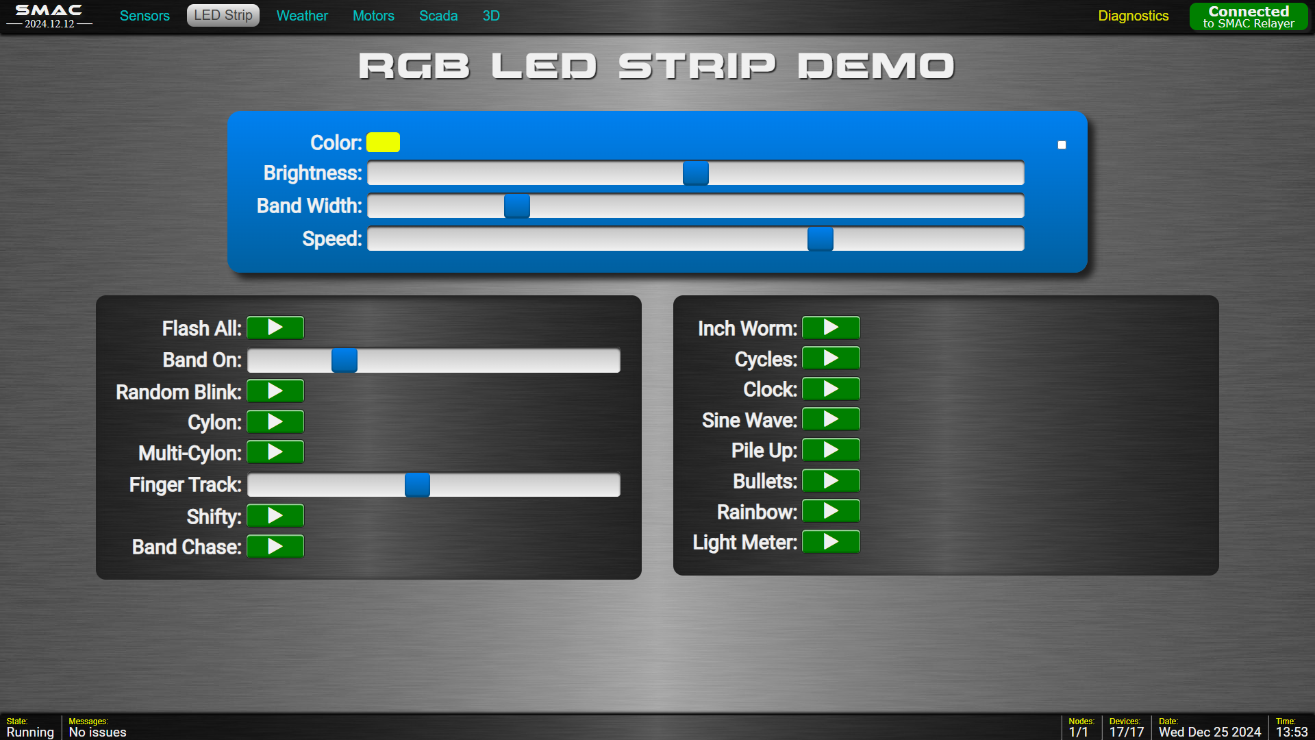
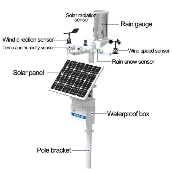
Weather Station Example
Diagnostics
examples
From here, you will see how all this comes together by going through some examples.
You will need at least two ESP32 Dev Boards for a SMAC System. One for a Relayer and at least one for a Node.
Start by creating a project folder on your local drive.
Then go to the SMAC GitHub Repo. In the Code section you should see two folders: Firmware and Interface.
Download a ZIP file of these two folders into your project folder:
∙ Under the Code Tab look for the green <> Code ▼ pulldown button
∙ Use the [Download ZIP] option to download into your project folder, then extract the zip file.
Your folder structure should look like this:
MyProject
  │
  ├── Firmware
  │     │
  │     ├── Node_Example1
  │     ├── Node_Example2
  │     └── Relayer
  │
  └── Interface (web app)
        │
        ├── Fonts
        ├── Images
        ├── Scripts
        ├── diagnostics.html
        ├── dsStyles.css
        ├── example.html
        ├── favIcon.ico
        ├── index.html
        ├── setMAC.html
        └── smacStyles.css
The Firmware folder holds the ESP32 code for Node/Device and the Relayer.The Interface folder holds the SMAC User Interface web app.
Our first example will demo simple telemetry by displaying a reading from a light sensor (photoresistor).
Building/Flashing
I use the Arduino framework in VS Code, but you're welcome to use PlatformIO or the Arduino IDE. In VS Code you will notice that the Arduino support by Microsoft is deprecated, but there is support from the Arduino Community. Install the Arduino Community Edition extension.
To use PlatformIO, move the header files into the include folder and all other files into the src folder. Also, rename the Node_Example1.ino file to main.cpp.
Let's turn one of your ESP32's into a SMAC Relayer.
Open the Firmware's Relayer folder and compile/flash to one of your ESP32's. You should now have a working Relayer and can be reused for all SMAC projects. The onboard RGB LED should be green. If not, you may have to change the pin for the LED. Look near the top of the common.h file for the #define STATUS_LED_PIN.
Now lets make your other ESP32 board a SMAC Node.
Close the Relayer folder and open the Node_Example1 folder. Compile/flash to the other ESP32 board.
For Nodes, the onboard LED stays red until it connects with the Relayer, then it goes green.
Example1
The hardware hookup for Node_Example1 is a voltage divider with a 5K resistor and a photoresistor (LDR).
(You can use any type of resistive sensor here, even just a pot.)
                     ~180Ω-1MΩ
          5KΩ           ↘↘
    ┌────█████────┬─────(▥)────┐
    │             │             │
    │             │             │
    ▲             ▼             ▼
  3.3V           GPIO          GND
                 pin 6
The firmware for Node_Example1 has a custom LightSensor class derived from the Device base class.The constructor saves and initializes the GPIO pin that our photoresistor will use. And it sets a default sampling rate.
Then the class overrides the DoPeriodic() method to return a reading. Data is returned by populating the "timestamp" and "value" fields of the global <DataPacket> structure. And a "ProcessStatus" is returned.
viewing local webpages
From here we'll be working in the Interface folder and the Chrome or Edge browser.
The easiest way I know of to view a website from your local drive
is to use Python's built-in web server:
- Install the latest version of Python onto your computer.
- Open a terminal window.
- Change directory to the home folder of your local website (the one with index.html).
-
Run the following command:
python -m http.server
This will start a server on port 8000 - Open Chrome or Edge and bring up localhost:8000
connecting your nodes to the relayer
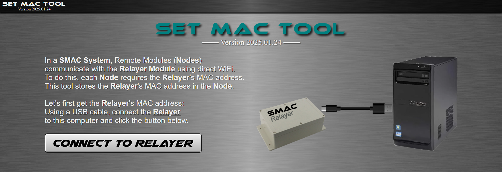
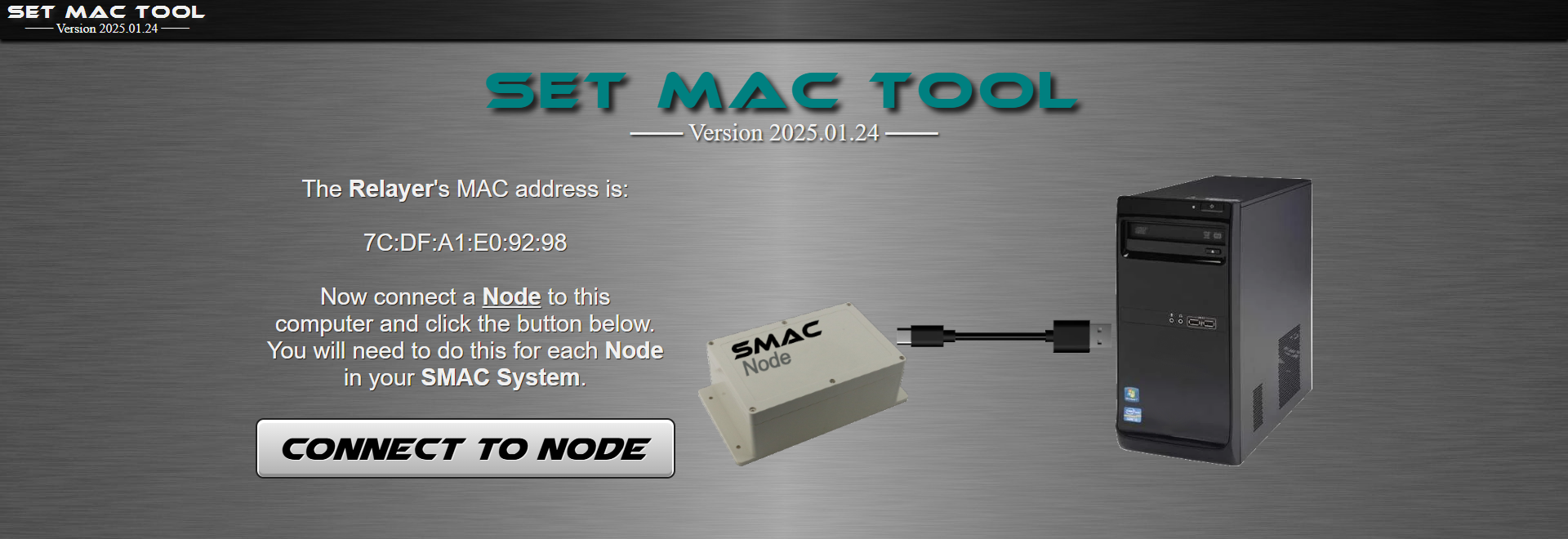
For your Nodes to wirelessly connect to the Relayer, they will need to know the Relayer's MAC address.
We will use the SMAC's Set MAC Tool to do this.
This tool grabs the MAC Address of the Relayer and stores it in the Node permanently.
You only have to do this once for each of your Nodes of your system.
Use your new Chrome Local or Edge Local shortcut to open a browser.
Press [Ctrl-O] to open the file setMAC.html in your project's Interface folder. (You can bookmark this page as the Set MAC Tool).
- Use a USB cable to connect your Relayer board to your PC and click the [Connect to Relayer] button.
- Choose the serial port your board is on.
- It will read the MAC address of the board.
- Then disconnect the Relayer and connect the Node board.
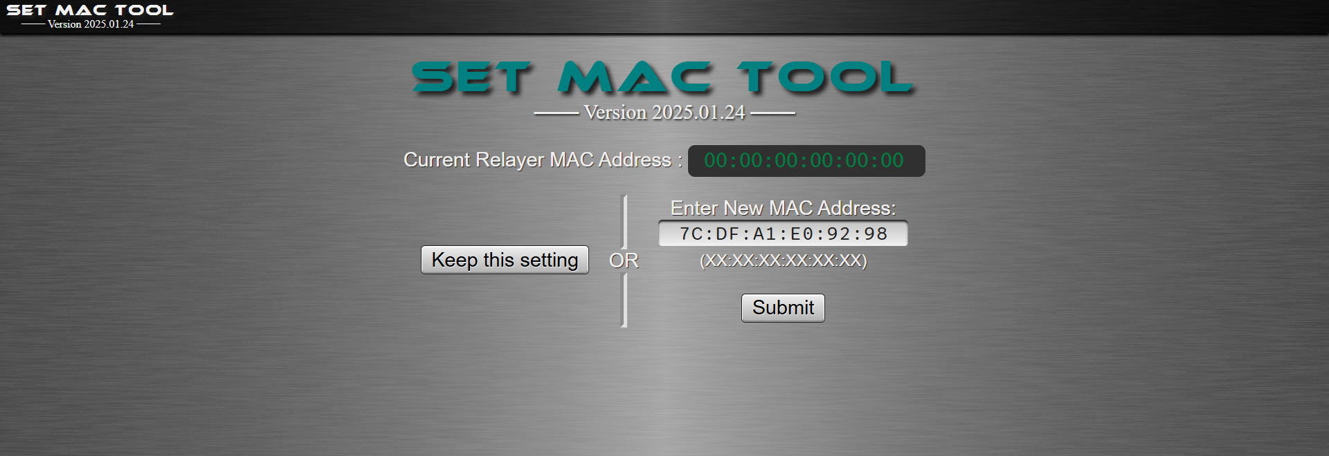
- Choose the serial port of the Node.
- It will read the current Relayer's MAC address stored on the Node board and ask to keep it or replace it.
- Submit the new MAC address if they don't match.
using the smac interface
Press [Ctrl-O] to open the file index.html in your project's Interface folder. (You can bookmark this page as the SMAC Interface).

Connect your Relayer to your PC.
Click on the [Connect to the Relayer] button and choose the serial port.
Once you connect to the Relayer the SMAC Interface for Example1 shows up.
Now power up your Node board with a USB power supply or battery.
The Node should connect to the Relayer and its LED should go green.
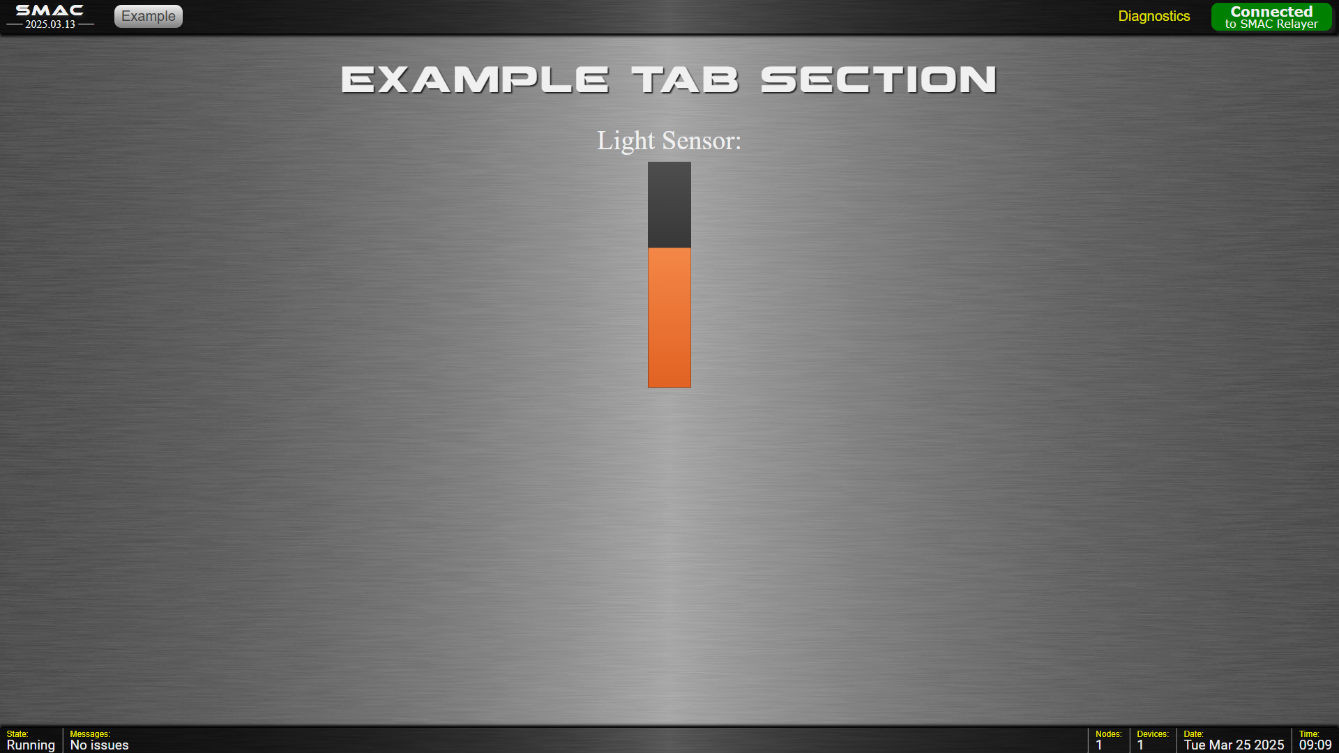
There is only one tab and one Device for this SMAC System.
It shows a "growbar" for the light sensor that is being updated 10 times per second.
(Wave your hand or flashlight over the light sensor)
The Diagnostics tab shows details about the system:
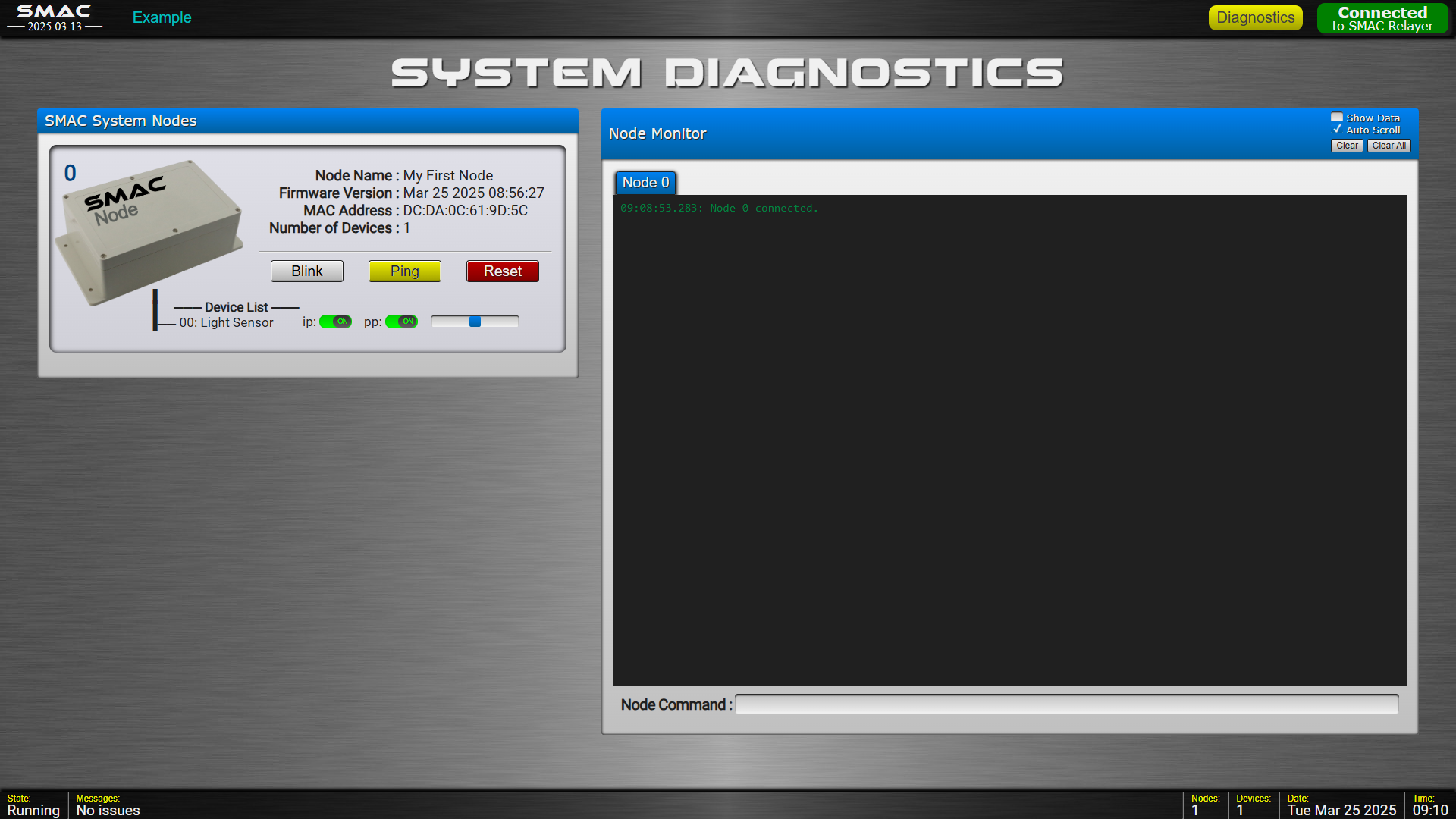
Notice the "Device List" for the Node. You can turn on/off both Immediate Processing and Periodic Processing and even set the data rate for Devices. You can also look at the data coming in by selecting "[] Show Data" in the Node Monitor title bar. You can also manually send commands directly to Devices in the "Node Command" box. (more on that later)
SMAC Interface Files
Since the SMAC Interface uses a tabbed control for your pages, you will need a single HTML file for each of your tab sections. There is no need for the <html>, <head> or <body> tags in your pages. You can simply have SMAC Widgets laid out as you wish.
In this first example there is only one tab page with a filename of example.html.
  Interface (web app)
    │
    ├── Fonts
    ├── Images
    ├── Scripts
    ├── diagnostics.html
    ├── dsStyles.css
    ├── example.html ◀────── added
    ├── favIcon.ico
    ├── index.html ◀──────── edit
    ├── setMAC.html
    └── smacStyles.css
You then need to edit the index.html file to include your tab pages:Open the index.html file and look for the "navButtons" section.
You will need a navButton for each of your tab pages:

Then scroll down a bit to this section.
You will need a content "div" for each page:

That's it. The SMAC Interface can now display your page by clicking on your tab button.
smac interface style
The UI style adopted by the SMAC Interface is called Skeuomorphism. This is to mimic some-what realistic control panels.
(Maybe I'm old fashioned but in my mind, a button should look like a button, and a switch should look like a switch.)
You can read more about Skeuomorphic design here, here, and here and see some examples here.
Your tab pages in the SMAC Interface are written in HTML, CSS and Javascript/jQuery. To visualize equipment components and data the Interface includes some built-in styles and SMAC Widgets. More about Widgets below ...
Some common CSS styles included are:
| dsLabelL/dsLabelM/dsLabelS | - blockish panel labels (large, medium, small) |
| dsDividerH/dsDividerV | - horizontal/vertical beveled seperator line |
| dsBlock/dsBlockRuled/dsBlockLowered/dsBlockRaised | - rounded corner section areas |
| dsGridForm | - form with labeled input fields |
| dsButton/dsButtonRound | - momentary buttons |
| dsInput | - all input types |
| dsSwitch | - sliding switch |
| dsSelect | - drop-down item selection |
| dsTable | - table with styled header |
| dsGroupbox/dsGroupBoxTitle/dsGroupBoxContent | - titled box area |
| dsTabControl/dsTabBar/dsTabButton/dsTabContent | - tab control with styled tab buttons |
Some SMAC Interface CSS styles included are:
| smac-ledOff/Red/Green/Blue/Yellow/Orange/Purple/White | - LED's |
| smac-panellightOff/Red/Green/Blue/Yellow/Orange/Purple/White | - panel lights |
| smac-eStop | - emergency stop button with reset |
| smac-digital | - seven-segment digital display |
| smac-display | - text area |
| smac-growbar | - vertical or horizontal "value" bar |
| smac-dial ☀ | - a rotary knob with printed values |
| smac-joystick ☀ | - a 2D dragging control |
☀ not yet implemented (I'm working on it ...)
... more coming soon ...
smac interface widgets
We display controls and visualize device data using SMAC UI Widgets.
SMAC Widgets are Custom HTML Web Components included with the SMAC Framework.
Some are implemented but many more are planned and coming soon.
SMAC Interface Widgets are added to your tabpage like any other HTML element.
The are two types of UI Widgets - Device Control Widgets such as a Switch and Data Display Widgets such as a Gauge.
Some Data Display Widgets can show data from more than one Device, such as a Graph.
Some Device Control Elements: (These HTML elements control devices)
| <smac-panelbutton> | - momentary push button |
| <smac-switch> | - on/off (binary) switch with any set of on/off images |
| <smac-eStop> | - emergency stop button with reset required |
| <smac-slider> ☀ | - single knob range selector |
| <smac-dualslider> ☀ | - dual knob low/high range selector |
| <smac-dial> ☀ | - rotary selection dial |
| <smac-spinner> ☀ | - value field using mouse wheel to adjust |
| <smac-joystick> ☀ | - 2D joystick |
☀ not yet implemented (I'm working on it ...)
... more coming soon ...
Some Data Display Elements: (These HTML elements react to device data)
| <smac-led...> | - colored LED's: Off, Red, Green, Blue, Yellow, Orange, Purple, White |
| <smac-panellight...> | - colored panel lights: Off, Red, Green, Blue, Yellow, Orange, Purple, White |
| <smac-flasher> ☀ | - flashing panel light with on/off time attributes |
| <smac-digital> | - single-device digital display (can use any font, e.g. 7-segment led) |
| <smac-odometer> ☀ | - spinning wheels with digits 0-9 |
| <smac-display> | - multiline display screen |
| <smac-growbar> | - single-device horizontal or vertical bar whose length represents the data value |
| <smac-gauge> | - single-device needle, filled pie slice or donut gauge |
| <smac-bargraph> ☀ | - multi-device bar graph |
| <smac-timegraph> | - multi-device cartesian graph with panning option (value vs. time) |
| <smac-devicegraph> ☀ | - device value vs. device value - such as voltage vs. temperature |
| <smac-polargraph> ☀ | - spider or radar Plot |
| <smac-piechart> ☀ | - a dynamic pie chart that updates its sections on the fly |
| <smac-donutchart> ☀ | - same as above |
| <smac-chartgraph> ☀ | - scrolling chart recorder |
| <smac-compass> | - a 360° nautical-type compass |
| <smac-bubblefield> ☀ | - variable sized semi-transparent circles |
| <smac-venndiagram> ☀ | - semi-transparent overlapping areas |
| <smac-bloomfield> ☀ | - sunburst? |
| <smac-camera> ☀ | - a digital camera web server streaming video or single photos |
☀ not yet implemented (I'm working on it ...)
... more coming soon ...
Each Widget has their own set of attributes for visual appearance, however, they require a "device" attribute to tie them to a specific Node and Device of your SMAC system.
The "growbar" in the example.html file is displayed using the <smac-growbar> widget with the following attributes:
<smac-growbar
device = "0,0" -- required: nodeID,deviceID
orientation = "vertical" -- vertical or horizontal
width = "3" -- 3% client area width
height = "30" -- 30% client area height
minValue = "0" -- mininum value from sensor
maxValue = "4095" -- maximum value from sensor
backColor = "#303030" -- background color
fillColor = "#FF8040"> -- bar color
</smac-growbar>
Nearly all Widgets require the 'device' attribute declaring where the data is coming from (nodeID,deviceID).
You can also add CSS styling to Widgets.
For example, let's display a light sensor reading in a digital field. Suppose our light sensor is physically on Node 0 and is Device 0. (The Node ID is zero and the Device ID is zero.) The HTML for this would be:
<smac-digital
device = "0,0">
</smac-digital>

(default style)
The device attribute takes two ID's separated with a comma - The Node ID and the Device ID.
(Attribute values are always in double quotes)
This simple HTML block will connect and display readings from Node 0/Device 0 in your tab page.
You could style this element using a normal CSS style attribute. For example:
<smac-digital style="padding:10px; border:2px solid blue; font-family:'Lucida Sans'; font-size:40px; color:aqua; background-color:#303030"
device = "0,0">
</smac-digital>

Suppose you want to turn a motor on/off with a switch.
We could have a motor driver on Node 0 as Device 1.
The HTML to control this motor would be:
<smac-switch
device = "0,1"
onImage = "Images/ui_Switch_Lever2_On.png"
offImage = "Images/ui_Switch_Lever2_Off.png"
onAction = "motorOnFunction()"
offAction = "motorOffFunction()">
</smac-switch>

Each time you toggle the switch, the function in onAction or offAction is called. Those functions could send a command to the motor driver as well as manipulate other components on your page, if necessary.
Sending Commands from the Interface
The Javascript SMAC function for sending commands to Nodes and Devices is
Send_UItoRelayer (nodeIndex, deviceIndex, command, params)
This is an asynchronous function so it should be used with the "await" keyword in front of it.
This function takes three or four parameters:
  nodeIndex   - a number from 0 to 19
  deviceIndex - a number from 0 to 99
  command     - 4-char command string (usually caps)
  params      - optional parameter string
The command is sent to the Relayer and forwarded to the targeted Node and Device
where it is picked up by the firmware's ExecuteCommand() method. We'll see how this is
done in the second example.Example2
Here we've added a momentary pushbutton and a yellow LED to the first example.
Hookup should look like the following:
                        470Ω
                  ┌─────█████─────┐
                  │               │
                  │               │
                  ▼               │
                 GPIO            (▼)  LED
                 pin 4           (─)↘
                                  │ ↘
         button                   │
    ┌────┬▀▀▀┬────┐               │
    │    └───┘    │               │
    │             │               │
    │             ▼               │
    │            GPIO    input    │
    │            pin 5 (pulldown) │
    │                             │
    │                             │
    │                ~180Ω-1MΩ    │
    │     5KΩ           ↘↘       │
    ├────█████────┬─────(▥)──────┤
    │             │               │
    │             │               │
    ▲             ▼               ▼
  3.3V           GPIO            GND
                 pin 6
In the Node_Example2 folder we've added Button and LED Device classes.Since we need to continually check if the button is being pressed, the Button class overrides the DoImmediate() method. And since we don't need to do anything periodically there's no need to override the DoPeriodic() method.
//--- Constructor -----------------------------------------
Button::Button (const char *inName, int inButtonPin)
:Device (inName)
{
// Init GPIO pin for a button
buttonPin = inButtonPin;
pinMode (buttonPin, INPUT_PULLDOWN); // Use pulldown resistor
// No need for Periodic processing
periodicEnabled = false;
}
//--- DoImmediate (override) ------------------------------
ProcessStatus Button::DoImmediate ()
{
// Store the latest reading in newState:
// Not doing any software debouncing here for simplicity
// Hardware debouncing should be done with an RC circuit
newState = digitalRead (buttonPin);
// Send DataPacket if button has changed state
if (newState != currentState)
{
// Send DataPacket
DataPacket.timestamp = millis ();
strcpy (DataPacket.value, (newState==0 ? "0" : "1"));
currentState = newState;
return SUCCESS_DATA;
}
return SUCCESS_NODATA;
}
For the LED class we do not need to do any processing but we will need to turn the LED on or off when commanded by the Interface.
So we override the ExecuteCommand() method.
//--- Constructor -----------------------------------------
LED::LED (const char *inName, int inLEDPin)
:Device (inName)
{
// Init GPIO pin
ledPin = inLEDPin;
pinMode (ledPin, OUTPUT);
// No need for Immediate or Periodic processing
immediateEnabled = periodicEnabled = false;
}
//--- ExecuteCommand (override) ---------------------------
ProcessStatus LED::ExecuteCommand ()
{
// Command info is held in the global <CommandPacket> structure.
// This method is only called for commands targeted for this device.
// First call the base class ExecuteCommand method
pStatus = Device::ExecuteCommand ();
// Check if command was handled by the base class
if (pStatus == NOT_HANDLED)
{
// The command was NOT handled by the base class,
// so handle custom commands:
//--- Turn On ---
if (strcmp (CommandPacket.command, "LEON") == 0)
{
// Turn on the LED pin
digitalWrite (ledPin, HIGH);
// Indicate successful and no data to return
pStatus = SUCCESS_NODATA;
}
//--- Turn Off ---
else if (strcmp (CommandPacket.command, "LEOF") == 0)
{
// Turn off the LED pin
digitalWrite (ledPin, LOW);
// Indicate successful and no data to return
pStatus = SUCCESS_NODATA;
}
}
// Return the resulting ProcessStatus
return pStatus;
}
And in the SMAC Interface we've added a graphical LED to indicate if the button is being pressed,
and a simple switch to turn on/off the yellow LED.
Also notice there are three Devices for our Node in the Diagnostics page now.
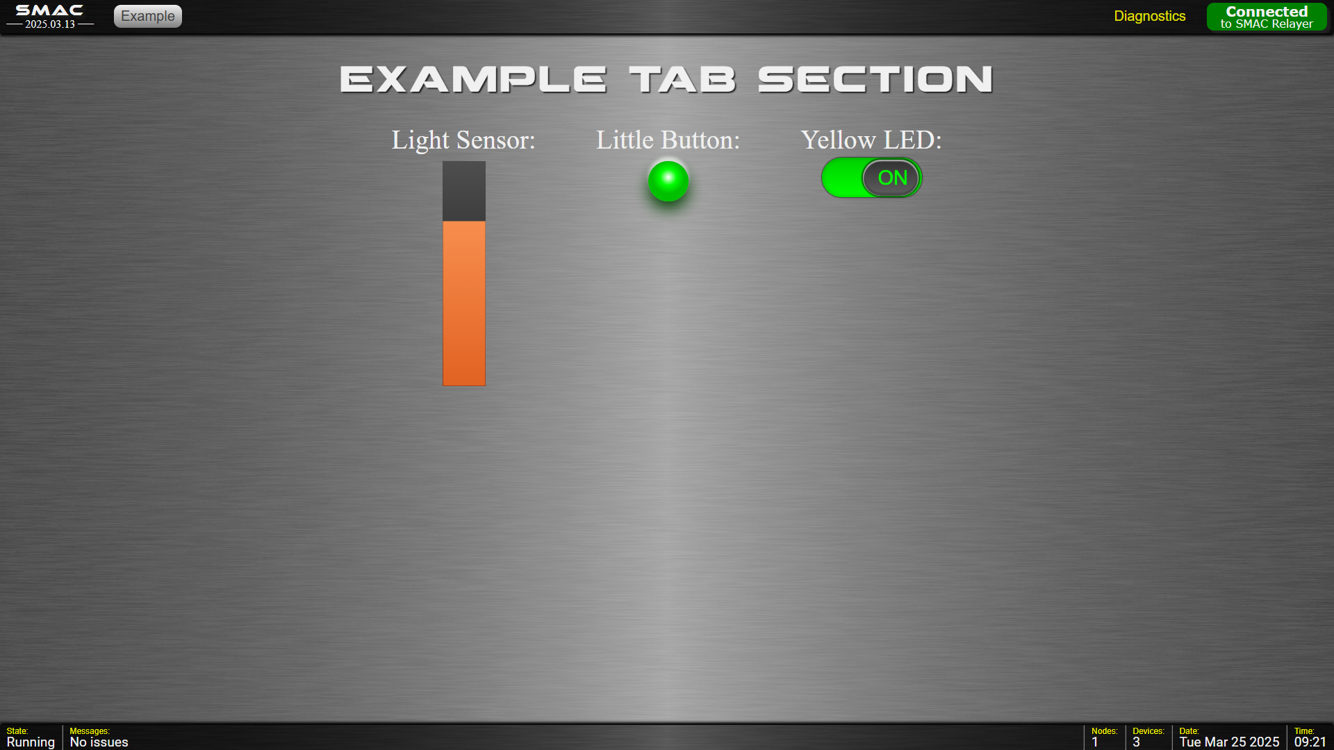
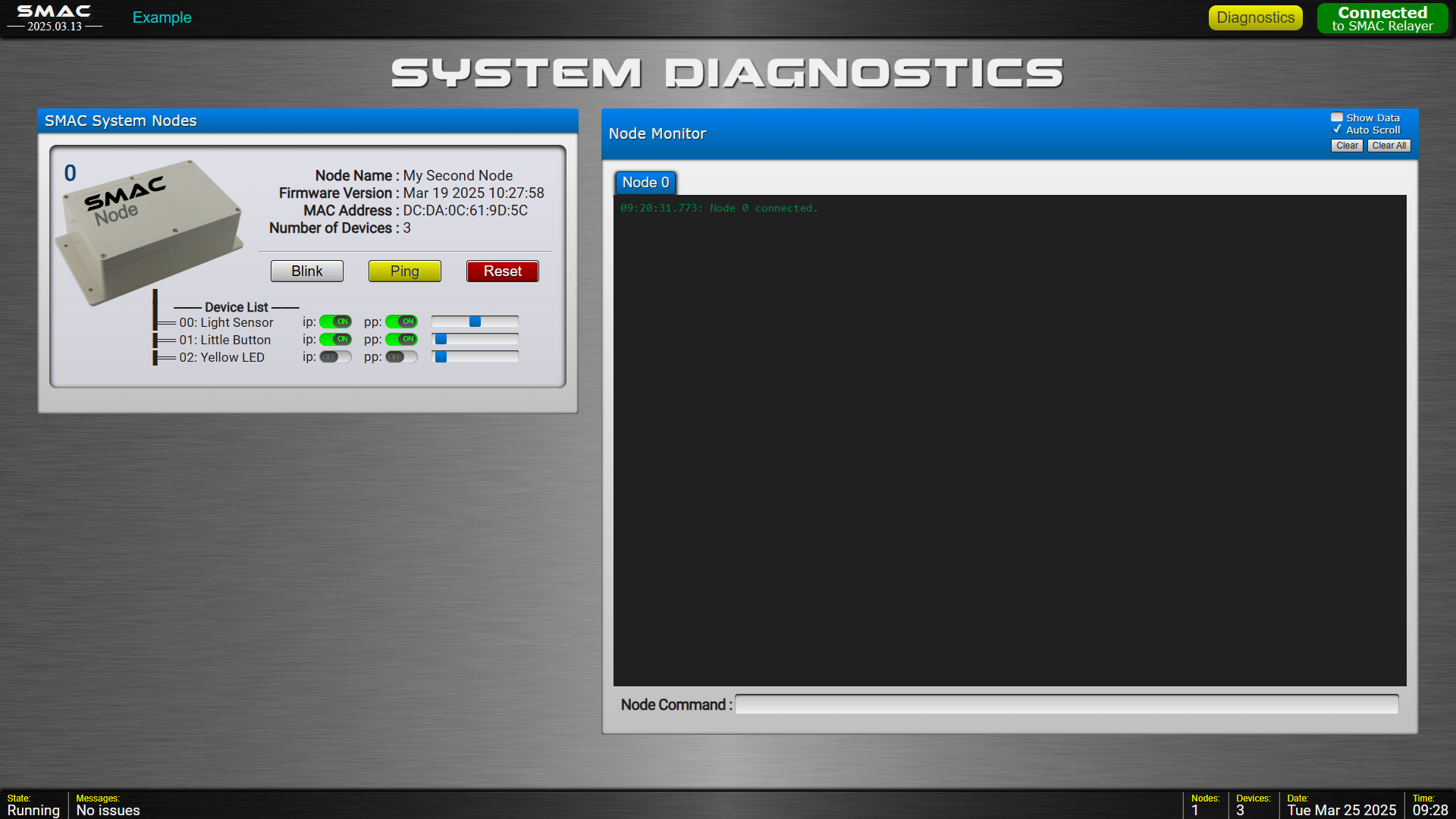
The HTML code in the example.html file now looks like this:
<br>
<div class="demoTitle">Example Tab Section</div>
<br>
<br>
<div style="font-size:2vw">
<!-- Light Sensor -->
<div class="dsBlock" style="margin:0 2vw; text-align:center">
Light Sensor:<br>
<smac-growbar style="margin-top:0.5vw"
device = "0,0"
orientation = "vertical"
width = "3"
height = "30"
minValue = "0"
maxValue = "4095"
backColor = "#303030"
fillColor = "#FF8040">
</smac-growbar>
</div>
<!-- Momentary Button -->
<div class="dsBlock" style="margin:0 2vw; text-align:center">
Little Button:<br>
<smac-led style="margin-top:0.5vw; font-size:3vw"
device="0,1">
</smac-led><br>
<br>
</div>
<!-- Yellow LED -->
<div class="dsBlock" style="margin:0 2vw; text-align:center">
Yellow LED:<br>
<input id="yellowLEDSwitch" type="checkbox" class="dsSwitch" style="margin-top:0.5vw; font-size:3vw" onchange="UpdateYellowLED()" />
</div><br>
<br>
</div>
<script>
async function UpdateYellowLED ()
{
try
{
const switchState = $("#yellowLEDSwitch").is(':checked');
if (switchState)
await Send_UItoRelayer (0, 2, 'LEON'); // Send command to turn Yellow LED on
else
await Send_UItoRelayer (0, 2, 'LEOF'); // Send command to turn Yellow LED off
}
catch (ex)
{
ShowException (ex);
}
}
</script>
Notice we've added a function to send a command to the LED Device; "LEON" for on and "LEOF" for off.
Since this function calls Send_UItoRelayer(), it should be an async function.
smac widget reference
A reference to each of the implemented SMAC Widgets is coming soon ...
For now, you can see what attributes are available in the SMAC_Widgets.js file of the Interface/Scripts folder.
●
●
●
If you like this framework, please Buy Me A Coffee ☕